Content
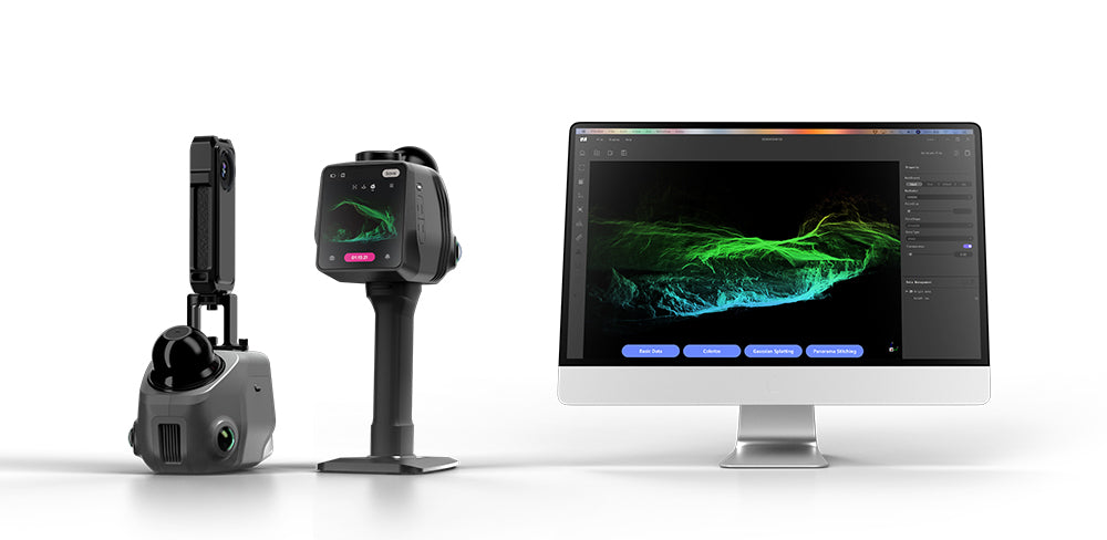
Just got your 3DMakerpro Raven LiDAR Scanner? In this article, we’ll walk you through the entire workflow step-by-step, from hardware setup and scanning to data export, and provide solutions to common issues.
Step 1: Hardware Setup & Familiarization
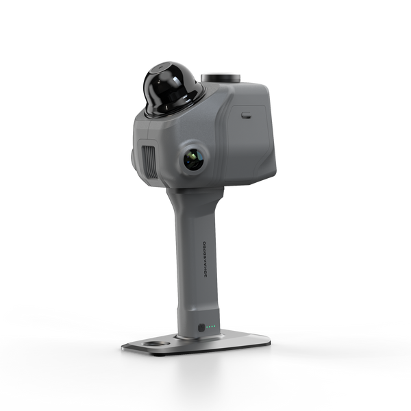
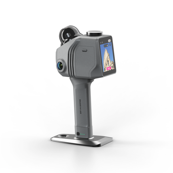
Take a moment to inspect your Raven LiDAR Scanner. Typically, the SD card is already pre-inserted into the device.
-
Battery Handle: Attach the battery handle to the scanner head; it snaps into place magnetically. (You may notice that the Raven is significantly lighter than the Eagle LiDAR Scanner!) To remove it, simply press the raised release button and pull the handle off.
-
Battery Check: Once the handle is connected, press the button on the bottom to check the battery level.
- Power On: The power button is located on the right side of the scanner. Press it to turn the device on. If you purchased the RTK module, be sure to install it on top of the scanner before proceeding.

Step 2: Learn Some Settings
Tap the Settings (adjustment icon) in the bottom-left corner of the screen. Here, you can configure the following parameters:
-
Scan Settings: We recommend setting both Accuracy and Point Density to Medium for standard use, though you can adjust these based on your needs. Note: These settings only affect the live display during scanning, not the final raw data.
-
Hotspot Links: ①Active hotspots: Enable remote data collection via mobile devices or wireless data transmission to a PC. The default network name is JMK6XXXXXXX / JMK7XXXXXXX, and the password is 12345678.
②Link hotspots: Used to receive third-party RTK differential positioning data. Turn this on, select a Wi-Fi network, enter the password, and tap Connect. (Note: The RTK function only works outdoors).
-
Calibration: Used for importing calibration files. Generally, no additional configuration is needed here, so you can leave it as-is.
- Storage: Check your available storage space and format the SD card if necessary.
-
General: Set your preferred Language (Chinese, English, French, Italian, and Japanes) and Timezone (switching the timezone will modify the timestamp of when your projects are created). You can also switch the Appearance between Dark and Light modes to suit your lighting conditions.
- Version: View device firmware information. If an update is available, a notification will appear here.

Step 3: Start Scanning
①Create a Project: Tap Scans and then Start. Enter a project name. If you are using the RTK module outdoors, toggle the GPS option on. Adjust your camera settings (e.g., enable night mode if needed) and tap Save.
②Adjust Lighting/Exposure: Choose between Indoor and Outdoor modes. Adjust the exposure slider to prevent the image from being overexposed or underexposed, then save.
③Initialization: If using RTK outdoors, wait a few minutes for the system to acquire a GPS signal. Once ready, hold the scanner completely level and still for 5 seconds to initialize the device.
④Begin Scanning: Start walking at a steady, natural pace. You can view the point cloud grid on the screen, or tap the camera icon in the bottom-right corner to switch to the real-world color feed.
During the scan, you can use the on-screen controls (from left to right):
-
Add Control Point: Tap to add marker points for later coordinate adjustments.
-
Delete Control Point
-
Front View
-
Top-down View
-
45°Oblique Top View
-
Split-screen View: Shows the point cloud and live camera feed simultaneously.
- Switch View: Toggle entirely between Live Feed and Point Cloud.
⑤Finish Scanning: Walk back to your original starting place to close the loop, then tap the Timer/Stop button to finish data collection.
⑥Preview Data: After stopping, you can drag the screen to inspect the raw data.
Initial View (Left): Resets the perspective to the original starting view.
Trajectory Line (Right): Shows or hides the path you walked during the scan.
⑦Tap Finish to save your project. Your saved project will now contain point cloud previews under the "Scans" tab and image previews under the "Photographs" tab.

Step 4: Export Data to Ray Studio
There are two ways to export your scanning data to your computer for processing:
Method A: SD Card Reader (Fastest for large files)
Remove the SD card from the scanner, insert it into a card reader, and copy the files directly to your computer.
Method B: Wi-Fi Hotspot (Recommended for convenience)
①Ensure the Active Hotspots option on your scanner is turned on (as mentioned in Step 2).
②On your computer, open your Wi-Fi settings and connect to the scanner's network (e.g., JMK6XXXXXX or JMK7XXXXXX / Password: 12345678).
③Open the Ray Studio software on your PC, and navigate to the Data Transmission page to verify the connection details if prompted:
- Hostname: Raven (or 192.168.20.110)
- Username: xxxxxx
- Password: xxxxxx
- Location: Choose the destination folder on your computer where you want to save the files.
④Click Connect; the scan files on your device will be displayed. Then download to transfer the files, and then open the project in Ray Studio to begin processing.

Step 5: Getting to Know the Ray Studio Interface
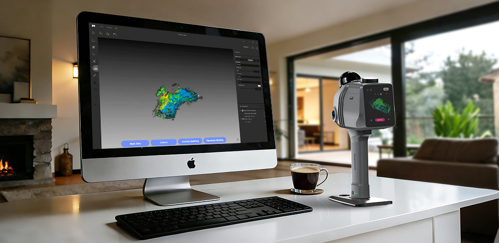
Before we process the data, let's familiarize ourselves with the Ray Studio workspace. The interface is highly intuitive and can be divided into a few main sections:
Left Side:
File Selection: Open projects or files, import calibration data, save, and exit.
(Note: The calibration file is saved natively on your scanner and will be automatically recognized when Ray Studio opens. If your file is ever corrupted—which is extremely rare—you can download it by clicking "Import Calibration" and entering your device's serial number.)
Display Selection: Toggle window views, zoom in (Ctrl+Up), zoom out (Ctrl+Down), or adjust standard camera angles.
Help Selection: Click this dropdown menu to access three options: Help opens quick links to the official Help Document and Company Website; Language allows you to switch the interface to English, Chinese, French, Italian, Japanese, or Russian; and About Us displays the current software version, release date, and your authorization information.
community website
Home: Return to the main project list interface.
Upload A Folder (Magnifying glass/folder): Open a local data folder.
Upload a File(Folder/arrow): Import local data files such as .amap, .ply, .pcd, .las, or .e57.
Save: Save your project.Export: Export your files (Note: You must select a file from the Data Management panel first).
Reset camera perspective: Readjusts the view and restores the point cloud data to the original top view in the center of the screen.
Window view: Switch between orthographic views (Front, Rear, Left, Right, Top, and Bottom).
Axis Lock: Lock the X, Y, or Z axis. Once locked, transformations cannot be applied in that specific direction.
First Person Browsing Perspective: Mimics the perspective of the human eye for a more realistic 3D walkthrough. You can use the W, A, S, D keys to navigate and view your data immersively.
Measurement: Point measurement, linear measurement, and volume measurement can be performed

Right Side:
Account: Log in to view your account status. If you subscribe to a plan, you can check your Gaussian Splatting export limits and available features here.
Calibration File: Displays the current device's calibration file (e.g., JMK6000059). You can click it to manually upload a calibration file (as mentioned earlier).
System Settings: Adjust the language, change the Rotation Center of Operation, view Shortcut Keys, and update the software version.
Screen Display: Toggle between full-screen and half-screen modes.
Background color: Toggle the background color (Black, Blue, Default, or Sky) according to your scene.
Point Size: Adjusts the size of the point cloud dots. A smaller value makes the data appear sharper and clearer.
Point Shape: Choose between Square and Round. Square points make colors pop out more vibrantly, while round points make it easier to observe the sparsity of your scan.
Color Type: Select RGB, the point cloud is displayed in actual color; Select Elevation, the point cloud color value can be used to represent the terrain; Select Intensity, the point cloud will be displayed from the perspective of weak and strong or pale and solid hue.
Transparency: Adjust the opacity of the point cloud from 0 (invisible) to 1 (solid). The default value of 0.25 is usually sufficient.
EDL: Enhances the display of feature contour information in point cloud data.
Shadow Strength: Controls the darkness of the shadows. (Default: 2.5)
- Higher values produce deeper, darker shadows with a more "solid" appearance.
- Lower values produce lighter, more transparent shadows with a "faint" appearance.
Shadow Radius: Controls the blurriness or softness of shadow edges. (Default: 2.5)
- Higher values produce softer, smoother shadow edges with a gentler transition.
- Lower values produce sharper, more defined shadow edges.

Next, we will continue to learn the Data Processing workflow. Note: Only after processing the data can we unlock the remaining tool functions.
Continuously updated...
Featured collection
LiDAR scanner
Raven LiDAR Scanner


Battery Grip